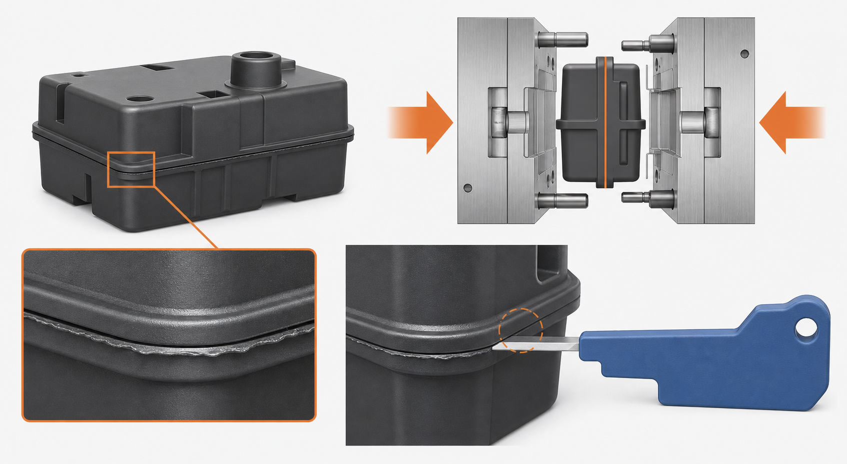
Flash in injection molding is unwanted thin plastic that extends beyond the intended part boundary, commonly at a parting line, shutoff, insert, ejector feature, vent or slide interface. It forms when molten material enters a gap or when cavity pressure opens a mold interface beyond its designed contact condition. The correct fix depends on whether the evidence points to process overpressure, mold wear, insufficient support, clamp limitation, venting, resin viscosity or part design.
For a buyer, flash should be defined by location, thickness, length, height, removal method and functional consequence. A small witness at a hidden edge may be acceptable, while the same amount on a seal, connector, latch, bearing seat or cosmetic face may be a rejection. A supplier should not simply trim flash and return the part without identifying why it formed and whether the condition will return during a sustained run.
What flash looks like and why it matters
Flash may appear as a thin fin along the parting line, a burr around an insert, a film at a vent, a raised edge near an ejector, or a feathered extension at a slide shutoff. The defect can be continuous or intermittent. It may occur on every cavity or only one cavity. A part that looks acceptable after manual trimming can still show dimensional drift, damaged shutoffs, increased labor or repeat flash after the tool continues to run.
Distinguish flash from an intentional parting-line witness, gate vestige, trimming burr or an edge that is designed to be removed. The drawing, approved sample and assembly function should define the boundary. If the flash appears after a tool change or gradually increases with production, mold contact and wear deserve priority. If it appears only at a high-pressure process condition, process and clamp evidence should be reviewed first.
Separate flash from similar edge conditions
| Observed feature | Possible mechanism | Useful confirmation |
|---|---|---|
| Thin fin at parting line | Parting-line gap, wear or mold deflection | Blue check, shutoff inspection and flash map by cavity |
| Flash around insert | Insert fit, support, alignment or pressure gap | Insert dimension, seating record and cross-section |
| Flash at vent | Vent too deep, damaged or over-pressurized | Vent depth, location, pressure and cosmetic limit |
| Small raised gate area | Gate vestige or gate trimming condition | Gate design, approved sample and removal method |
| Burr after ejection | Ejector edge, part drag or tool damage | Ejector inspection, release force and edge condition |
| Intermittent flash after long run | Thermal growth, wear, contamination or clamp variation | Time, cavity, tool temperature and maintenance records |
Use the common injection molding defects guide for the broad defect overview. The mold design and mold making guide supports shutoff and maintenance decisions, while the injection molding service page covers the production route. This page is specific to flash diagnosis, parting-line evidence and the decision between process adjustment and mold correction.
Flash cause, evidence and corrective action
| Cause group | Evidence to collect | Correction direction |
|---|---|---|
| Process pressure | Peak cavity pressure, transfer point, packing, melt temperature and fill speed | Stabilize pressure and transfer without creating short shots or sink |
| Clamp and machine | Clamp force, mold protection, platen parallelism and machine repeatability | Confirm adequate clamp capacity and protect the mold from overload |
| Mold fit | Parting-line blue check, shutoff contact, insert fit and mold deflection | Spot, support or repair the tool only after locating the gap |
| Wear and maintenance | Flash growth, cycle count, steel hardness, polishing and previous repair | Restore the worn interface and record a controlled requalification |
| Material and geometry | Viscosity, grade, wall thickness, venting and flow direction | Review resin, wall transitions, vent depth and pressure demand |
The correction should follow the location. Flash at the same parting-line segment across all cavities points toward mold contact or deflection. Flash only in one cavity suggests cavity-specific wear, insert alignment or runner balance. Flash at a vent may mean the vent is too deep or that pressure is too high at the end of fill. Flash around an insert requires a fit and support review, not only a lower packing pressure.
Diagnostic sequence for a flash complaint
- Define the limit. Mark the location, maximum allowed thickness or height, removal method and functional consequence on the drawing or boundary sample.
- Map the defect. Record cavity, shot number, machine, time in run, location and whether the flash is continuous or intermittent.
- Check the process. Review fill profile, transfer, packing, melt temperature, cavity pressure and clamp force.
- Inspect the interface. Use a blue or feeler check where suitable, inspect shutoffs, parting lines, slides, inserts, vents and ejector edges.
- Compare cavities. Photograph and measure the same feature in every cavity to prevent an average from hiding one weak cavity.
- Check tool history. Review cycle count, steel repair, polishing, insert replacement, lubrication and maintenance intervals.
- Run a controlled trial. Change the smallest relevant variable group, then verify flash, dimensions, fill, sink, weld lines and cycle stability.
Do not solve flash by reducing clamp force or packing pressure without checking whether the part still fills and meets dimensional requirements. A lower pressure can hide the defect in one sample while creating a short shot or weak weld line. Likewise, increasing clamp force may mask a worn shutoff and increase tool stress. The objective is a stable tool and process condition, not a temporary visual improvement.
Process corrections
Transfer position, fill speed and packing pressure should be reviewed together. If the mold is nearly full when pressure transfers, a small change in transfer can change peak pressure at the parting line. A staged fill profile may reduce pressure at a sensitive shutoff while preserving filling in thin areas. Melt temperature affects viscosity and pressure demand, but it also affects flash sensitivity and material degradation. Every trial should record part weight, pressure, dimensions and defect location.
- Verify repeatable transfer position, cushion and shot size.
- Review packing pressure and time against part weight and critical dimensions.
- Use a fill profile that protects sensitive shutoffs without starving thin walls.
- Control melt and mold temperature to reduce viscosity variation.
- Confirm mold protection and clamp force are repeatable at production speed.
- Separate cavity-specific flash from machine-wide process changes.
Mold and DFM corrections
Parting lines need enough support to resist the pressure created by the actual geometry and resin. Thin shutoffs, unsupported inserts, long slides and narrow sealing lands can deflect even when the tool looks rigid on the bench. The mold review should consider steel support, shutoff angle, land width, cavity pressure, venting, thermal growth and maintenance access together.
DFM can reduce risk by moving a parting line away from a seal or cosmetic edge, adding support behind a shutoff, improving insert seating, balancing wall thickness and avoiding a high-pressure flow front against a weak interface. Vents should release air without becoming a new flash location. For glass-filled or abrasive resins, steel choice and wear monitoring are part of the flash-control plan.
A tool modification should be based on a measured gap or wear location. Spotting, polishing or welding without a controlled reference can shift the flash to another region. Record the steel removed or added, the repair area, the polishing direction and the requalification samples. A supplier should state whether the repair changes the parting line, datum, texture or cosmetic boundary.
Validation and acceptance plan
Inspect flash by cavity and by production interval. Measure thickness or height with a suitable optical system, microscope, gauge or CMM method, and avoid deforming a thin fin during measurement. For functional areas, include assembly, sealing, electrical contact, latch or flow tests. For cosmetic areas, use a controlled viewing distance, light source and approved boundary sample.
After a mold repair or process correction, run enough consecutive shots to expose thermal growth, cavity variation and repeatability. Retain first-off, steady-state and end-of-run samples. The report should link flash measurement to cavity, machine, resin lot, cycle count and inspection condition. If manual trimming remains acceptable, define the trimming tool, operator method, residual limit and labor expectation.
Flash prevention and RFQ checklist
- Provide CAD and drawing with parting line, seal, cosmetic and no-flash zones marked.
- State resin grade, filler, expected viscosity range and annual volume.
- Identify cavity count, machine constraints, clamp range and automation expectations.
- Ask for shutoff, insert, vent, parting-line and mold-deflection risk comments.
- Define flash thickness, height, length, location and removal requirements.
- Require cavity-specific inspection and a sustained production sample.
- Record mold maintenance, steel repair, polishing and cycle-count history.
- Agree the approval process for any change to the parting line or functional edge.
For an RFQ or corrective-action request, send part photos, cavity and shot information, controlled drawing, resin and grade, process sheet, annual volume, mold history and the assembly function affected by flash. This gives the supplier enough information to separate pressure, clamp, wear, vent and geometry causes before recommending a repair.
Flash: Decide Whether the Cause Is Process, Tool or Design
| Flash Location | Evidence to Compare | Practical Response |
|---|---|---|
| Parting line or shutoff | Gap, blue-check contact, cavity pattern, clamp and pressure data | Stabilize the process, then inspect fit, support and wear |
| Insert or slide interface | Insert seating, mismatch, thermal growth and cavity-specific results | Correct support, alignment or steel condition |
| Vent land | Vent depth, burn or gas evidence, end-of-fill pattern and maintenance record | Review vent geometry and clean condition without simply closing the vent |
| Thin edge or cosmetic boundary | Part thickness, packing response, resin viscosity and edge support | Review DFM, fill and packing before adding a trimming operation |
Flash is often treated as a pressure problem because pressure is easy to change. That can hide a damaged shutoff, worn insert, deflected mold, oversized vent or unsupported edge. A sound corrective action identifies the location, cavity, cycle count and measured flash limit, then proves the change with consecutive production-intent shots.
How Nylon Plastic Supports Flash Reduction
Nylon Plastic reviews modified nylon material behavior together with mold fit, process control and inspection. PA-GF20 and PA-CF30 may increase tool wear and change filling behavior, so the resin, filler, gate, vent, shutoff and maintenance interval should be considered as one system.
- Define no-flash zones, functional edges, cosmetic limits and any acceptable trimming method.
- Separate a resin or process correction from a repair that changes the parting line or shutoff.
- Link cavity-specific inspection, mold maintenance and sample approval to the controlled revision.
Bài đọc liên quan
Câu hỏi thường gặp
What is the fastest way to confirm flash?
Map flash by cavity and location, measure its thickness or height, review pressure and clamp records, and inspect the parting line, shutoffs, vents and inserts with a suitable method.
Can flash be fixed by process settings alone?
Sometimes pressure, transfer, temperature or fill changes remove flash when the mold interface is sound. Persistent or cavity-specific flash usually needs a fit, wear or maintenance review.
When does flash require a mold modification?
Consider mold work when a measured gap, worn shutoff, damaged vent, insert mismatch or mold deflection remains after a stable process window is established.
How should flash be measured or accepted?
Define thickness, height, length, location, viewing condition and functional consequence. Confirm sealing, assembly or cosmetic requirements with repeated samples.
Does increasing clamp force always remove flash?
No. More clamp force can hide a mold-fit problem, increase machine or tool load and still leave flash at a vent, insert or unsupported edge. Find the location and cause first.
Request a Flash Troubleshooting Review
Send part photos, the controlled drawing, resin and grade, cavity information, process and clamp records, mold history, annual volume and the affected function.