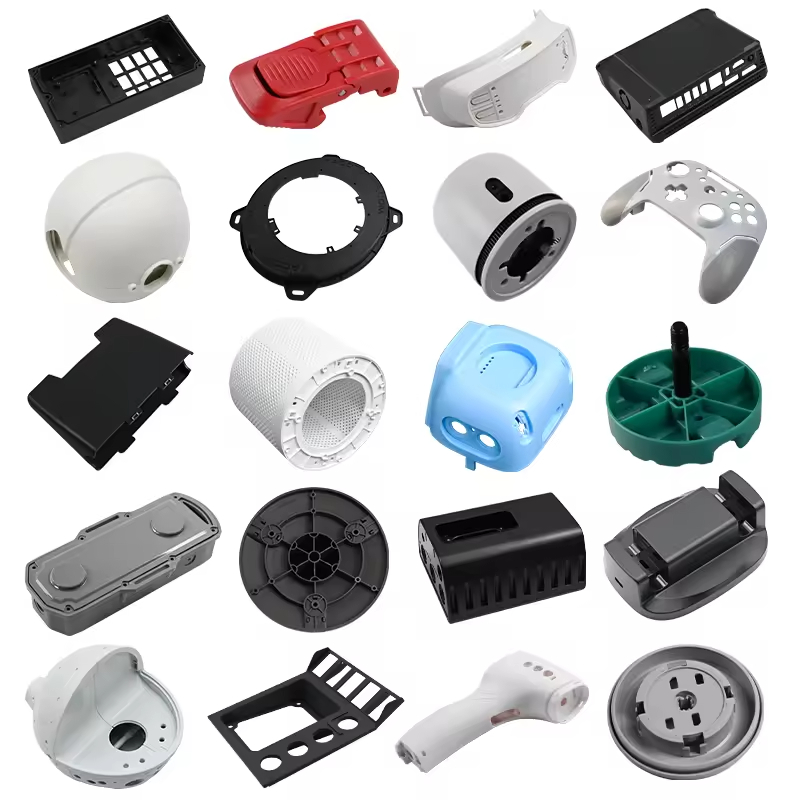
Giới thiệu về thiết kế khuôn ép phun
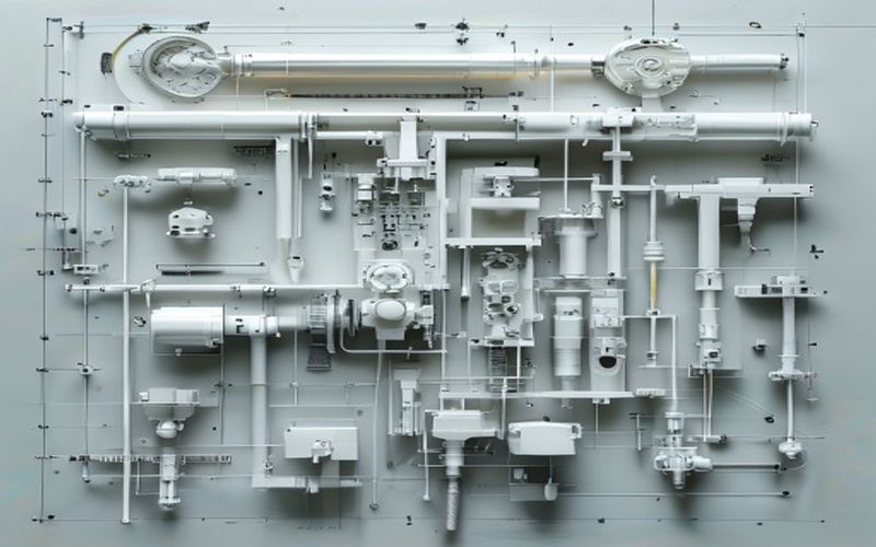
Thiết kế khuôn ép phun là nền tảng cho việc sản xuất thành công các chi tiết nhựa. Một khuôn được thiết kế tốt đảm bảo chất lượng chi tiết ổn định, chu kỳ sản xuất hiệu quả và tuổi thọ khuôn cao. Hướng dẫn này trình bày những nguyên tắc cơ bản mà mọi kỹ sư cần nắm vững.
1. Độ dày thành đồng nhất
Việc duy trì độ dày thành sản phẩm đồng đều là yếu tố quan trọng trong quá trình ép phun. Sự chênh lệch về độ dày sẽ gây ra hiện tượng làm nguội không đồng đều, dẫn đến hiện tượng cong vênh, vết lõm và ứng suất bên trong.
Độ dày tường khuyến nghị theo loại vật liệu
| Chất liệu | Độ dày khuyến nghị (mm) |
|---|---|
| ABS | 1,2 – 3,5 |
| PP | 0,8 – 3,8 |
| Máy tính cá nhân | 1,0 – 3,8 |
| Nylon (PA6/PA66) | 0,8 – 3,0 |
| POM | 1,0 – 3,0 |
2. Góc cắt để tháo khuôn
Góc nghiêng giúp các chi tiết đúc có thể tách ra khỏi khoang khuôn một cách trơn tru. Nếu không có góc nghiêng phù hợp, các chi tiết có thể bị dính, dẫn đến lỗi sản phẩm và hư hỏng khuôn.
- Chiều sâu mớn nước tối thiểu: 0,5° – 1° đối với bề mặt nhẵn
- Bề mặt có hoa văn: 2° – 5° tùy thuộc vào độ sâu của kết cấu
- Các tính năng nâng cao: Tăng độ dày để bù đắp cho sự co ngót của vật liệu
3. Thiết kế xương sườn phù hợp
4. Chiến lược bố trí cổng
Vị trí đặt cổng hàn ảnh hưởng đến mô hình lấp đầy, đường hàn và bề mặt chi tiết. Cần lưu ý:
- Chiều dài dòng chảy: Giảm thiểu để giảm sụt áp
- Vị trí đường hàn: Vị trí tại các khu vực không quan trọng
- Hình thức: Nếu có thể, hãy giấu các cổng ở những khu vực không dễ thấy
- Chức năng của bộ phận: Tránh lắp đặt cổng gần các cấu trúc chịu lực
5. Thiết kế hệ thống làm mát
Hệ thống làm mát hiệu quả giúp rút ngắn thời gian chu kỳ và nâng cao chất lượng sản phẩm. Các yếu tố cần lưu ý:
- Khoảng cách đều đặn giữa các kênh làm mát (2–3 lần đường kính kênh)
- Các tấm chắn và thiết bị tạo bọt cho lõi khoan sâu
- Làm mát theo hình dạng cho các cấu trúc hình học phức tạp
- Tốc độ dòng chảy thích hợp (chế độ dòng chảy nhiễu loạn)
Những sai lầm thường gặp trong thiết kế cần tránh
- Các đường cắt dưới không có cơ chế phù hợp (bộ nâng, thanh trượt)
- Các góc trong nhọn gây ra hiện tượng tập trung ứng suất
- Hệ thống thông gió không đủ dẫn đến hiện tượng cháy và sản phẩm không đầy khuôn
- Không tính đến sự co ngót vật liệu trong các tính toán kích thước
Kết luận
Việc tuân thủ các nguyên tắc thiết kế khuôn ép này sẽ đảm bảo các chi tiết sản xuất được với chất lượng ổn định. Sự hợp tác từ sớm giữa các nhà thiết kế sản phẩm và kỹ sư khuôn sẽ giúp tránh được những thay đổi tốn kém về sau.
Tài nguyên liên quan
- Gia công CNC nylon
- In 3D để tạo mẫu so với sản xuất
- Hướng dẫn lựa chọn vật liệu nhựa
- Các yếu tố ảnh hưởng đến chi phí nhựa kỹ thuật
- So sánh giữa PEEK và PEI
Tài nguyên liên quan
- Gia công CNC nylon
- In 3D để tạo mẫu so với sản xuất
- Hướng dẫn lựa chọn vật liệu nhựa
- Các yếu tố ảnh hưởng đến chi phí nhựa kỹ thuật
- So sánh giữa PEEK và PEI
Tài nguyên liên quan
- Gia công CNC nylon
- In 3D để tạo mẫu so với sản xuất
- Hướng dẫn lựa chọn vật liệu nhựa
- Các yếu tố ảnh hưởng đến chi phí nhựa kỹ thuật
- So sánh giữa PEEK và PEI
Câu hỏi thường gặp
When does Injection Mold Design Principles — Building Quality Molds from the Ground Up make sense?
Injection Mold Design Principles — Building Quality Molds from the Ground Up makes sense when the part volume, material choice, geometry, and repeatability needs justify mold design and tooling investment.
What design factors matter most for Injection Mold Design Principles — Building Quality Molds from the Ground Up?
Độ dày thành, gân, phần lồi, góc nghiêng, vị trí cửa rót, độ co ngót, đường phân chia và cơ chế đẩy đều ảnh hưởng đến chất lượng chi tiết đúc.
Cần những thông tin nào trước khi sản xuất khuôn?
Nhà cung cấp cần xác nhận mô hình 3D, vật liệu, khối lượng dự kiến hàng năm, các yêu cầu về hình thức, yêu cầu về dung sai, cũng như bất kỳ yêu cầu nào liên quan đến lắp ráp hoặc kiểm tra chức năng.
What is the biggest risk in Injection Mold Design Principles — Building Quality Molds from the Ground Up?
Rủi ro lớn nhất là phê duyệt khuôn mẫu trước khi các yếu tố như tính chất vật liệu, độ co ngót, quá trình chảy và chức năng của chi tiết được kiểm tra đầy đủ dựa trên điều kiện ứng dụng thực tế.
How to Review an Injection Mold Design Before Steel
A good mold design review connects the molded part to the actual production machine, resin, cycle, inspection method and expected tool life. A drawing can look complete while still leaving important decisions open: where the gate will be placed, how air will leave the cavity, how the part will be released, how cooling will reach thick sections and how worn components will be replaced. Before steel is cut, ask for a review that explains these decisions in relation to your part requirements.
Start with the controlled part drawing and mark critical-to-function dimensions, sealing surfaces, assembly datums, cosmetic zones, inserts and areas that cannot show ejector marks or gate vestige. Add the resin grade, filler content, color, annual volume, target cycle and molding machine limits. These inputs determine whether a simple single-cavity tool, a multi-cavity tool, a family mold or a more automated solution is appropriate.
| Design area | Buyer risk | Evidence to request |
|---|---|---|
| Parting line and shutoffs | Flash, mismatch, sealing damage or an unacceptable cosmetic line | Parting-line mark-up, shutoff angles and sample standard |
| Gate and runner | Weld lines, air traps, poor packing, fiber orientation or visible vestige | Gate location, fill direction and runner-balance concept |
| Cooling layout | Long cycle, uneven shrinkage, sink, warpage or local overheating | Cooling circuit drawing and temperature-control assumptions |
| Ejection | Sticking, deformation, drag marks or pin witness on a critical surface | Ejector map, draft review and release-force plan |
| Maintenance access | Long downtime when wear parts or slides need service | Replaceable insert list, spare parts and service access |
Gate, Venting and Cooling Decisions
Gate location should follow the part’s functional and cosmetic priorities. A gate near a thick section may improve packing but can increase sink or vestige. A gate on a cosmetic face may shorten flow length but create an appearance problem. For glass-filled resin, the flow direction can influence stiffness, shrinkage and anisotropy. Multi-cavity tools also need a balanced runner system so each cavity receives a consistent melt history.
Venting is part of the filling design, not a late repair. End-of-fill areas, deep ribs, blind pockets, slides and weld-line regions need a practical escape path for air and gas. Inadequate venting can show up as burn marks, short fill, gloss differences or unstable filling. Ask how vents will be machined, cleaned and protected during maintenance.
Cooling should cover thick bosses, ribs, inserts and areas near the gate while keeping sufficient steel around the cavity. The circuit should be reachable for cleaning and leak checks. Baffles, bubblers or conformal channels may be considered when conventional drilling cannot control temperature. The best choice depends on cycle target, part geometry, steel layout and the value of reducing dimensional variation.
Tool Architecture and Steel Selection
Tool architecture should match volume and resin severity. Prototype and low-volume programs often benefit from accessible inserts and a design that can be changed after the first trial. Higher-volume programs usually need robust cavity details, balanced cooling, reliable automation interfaces and serviceable wear components. For abrasive or corrosive materials, cavity steel, hardness, surface treatment and replaceable gates deserve a documented decision.
| Project condition | Design emphasis | Questions for the quotation |
|---|---|---|
| Prototype or pilot | Fast changes and accessible inserts | Which features can be adjusted after T1? |
| Repeat production | Cycle stability, balance and maintenance access | What shots, cycle and service interval are supported? |
| Abrasive engineering resin | Wear resistance at gates, slides and shutoffs | Which steel and spare inserts are included? |
| Tight cosmetic requirement | Gate, polish, texture, vent and parting-line control | What sample is used for appearance approval? |
Trial, Inspection and Tool Acceptance
A mold should be accepted against an agreed trial plan, not only because the machine produces a part. Record resin grade and lot, machine, mold temperature, melt temperature, injection profile, holding conditions, cycle and cavity identification. Review short shots, flash, sink, burn marks, weld lines, ejection, warpage and dimensions. For multi-cavity tools, inspect cavity-to-cavity variation instead of relying on one representative part.
Before production release, request the approved mold drawing, steel and component list, cooling and pneumatic diagrams, cavity identification, spare-parts list, maintenance instructions and dimensional report. Critical features should be measured with the agreed datum and conditioning state. If a dimension is affected by moisture or temperature, define when the measurement is taken. We can support DFM review, mold design, fabrication, sampling and corrective changes as one connected project.
For an RFQ, send CAD, controlled drawing, resin data, volume, target cycle, machine information, cosmetic zones, critical dimensions, inserts, post-molding assembly and required tests. A complete input package allows a mold supplier to price the actual risk rather than adding broad assumptions to the quotation.