Dung sai in 3D tốt đến từ sự kết hợp hài hòa giữa khả năng của máy, tính chất vật liệu và thiết kế lắp ghép. Công nghệ in 3D FDM mang lại sự tự do thiết kế đáng kinh ngạc, nhưng khi nói đến độ chính xác — tức khả năng duy trì dung sai ổn định — nó vẫn còn hạn chế so với các phương pháp sản xuất truyền thống như gia công CNC hay ép phun. Đối với các kỹ sư thiết kế các bộ phận chức năng phải khớp nối, trượt, lắp ráp hoặc tạo kín, việc hiểu rõ độ chính xác mà công nghệ FDM có thể đạt được một cách thực tế — và cách thiết kế phù hợp với chúng — là điều thiết yếu.
Hướng dẫn này bao quát mọi khía cạnh, từ nguyên nhân gốc rễ của sai số kích thước đến các bảng dung sai có thể in, quy trình hiệu chuẩn, cũng như các chiến lược thiết kế cho các loại ghép ép, ghép trượt và cụm lắp ren. Nếu biến dạng nhiệt cũng là một phần của vấn đề, thì Hướng dẫn khắc phục hiện tượng cong vênh khi in 3D là một công cụ hỗ trợ hữu ích vì các sai số về độ phẳng và độ khớp thường có cùng nguyên nhân gốc rễ.
Tại sao dung sai FDM lại quan trọng đối với các bộ phận chức năng
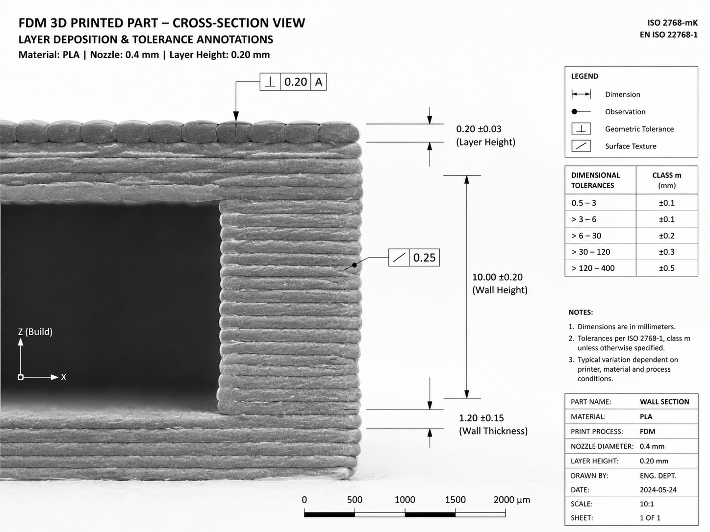
Khác với ép phun hay gia công CNC — nơi độ dung sai ±0,05 mm là điều bình thường — công nghệ FDM hoạt động theo một cơ chế khác. Sự kết hợp giữa quá trình đùn polymer nóng chảy, lắng đọng từng lớp và co ngót nhiệt tạo ra sự biến động kích thước vốn có. Nếu bạn thiết kế một lỗ với độ dung sai dự kiến là ±0,1 mm nhưng máy in của bạn lại cho ra kết quả ±0,5 mm, thì việc lắp ráp sẽ không thành công. Thiết kế cho công nghệ FDM có nghĩa là phải hiểu rõ khả năng thực tế của máy in và từ đó áp dụng các chiến lược lắp ghép phù hợp để bù đắp cho những hạn chế đó.
Nguyên nhân gốc rễ của sai số kích thước trong công nghệ FDM
| Nguồn lỗi | Đóng góp điển hình | Đặc điểm |
|---|---|---|
| Sự dao động đường kính sợi | ±0,05 mm trên mỗi mặt tường | Có hệ thống, nhất quán trên các tầng |
| Co ngót do nhiệt (co lại) | 0,2% – 0,8% tuyến tính | Tỷ lệ thuận với kích thước chi tiết; phụ thuộc vào vật liệu |
| Lượng tử hóa động cơ bước | ±0,0125 mm trên mỗi mm | Có tính xác định; có thể hiệu chỉnh để loại bỏ |
| Khoảng hở cơ học | ±0,05 – 0,2 mm | Phụ thuộc vào hướng; tình trạng tồi tệ hơn trên các máy đã cũ |
| Sự không đều của trục vít dẫn hướng trục Z | ±0,02 – 0,1 mm trên mỗi 100 mm | Định kỳ; có thể phát hiện được trong các khối hiệu chuẩn |
| Lượng tử hóa chiều cao lớp | ±0,5 × chiều cao lớp | Chỉ áp dụng cho các đặc tính theo phương thẳng đứng; ảnh hưởng đến độ tròn của lỗ |
Khả năng đáp ứng dung sai FDM thực tế theo từng loại máy in
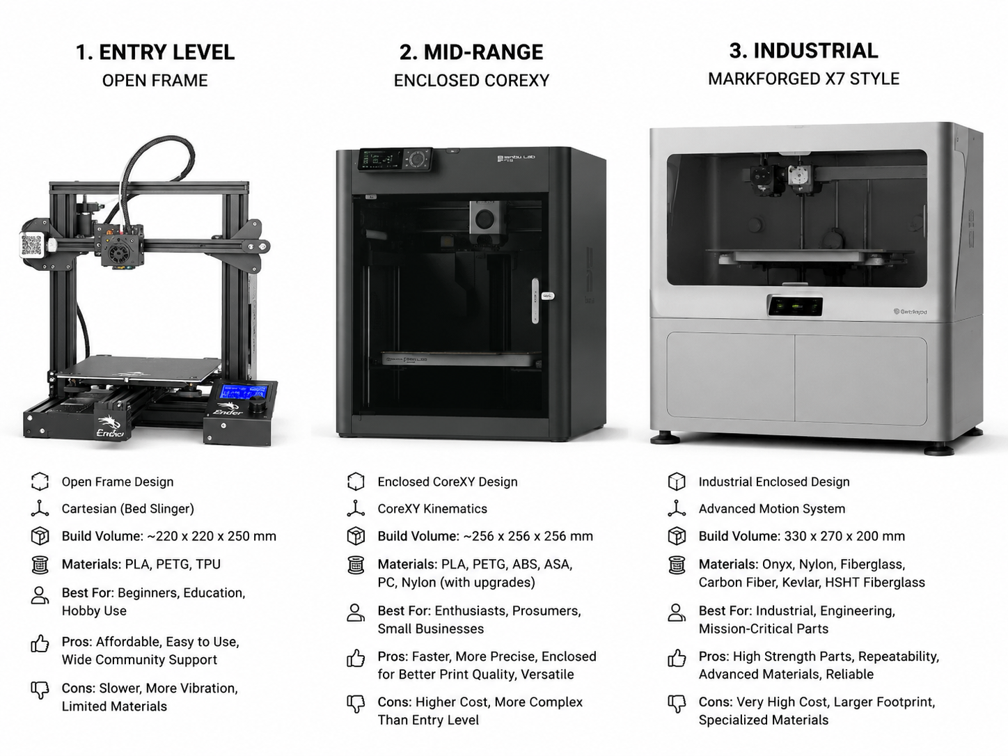
| Lớp máy in | Dung sai XY | Dung sai Z | Độ chính xác của lỗ | Tính năng tối thiểu |
|---|---|---|---|---|
| Dòng máy dành cho người mới bắt đầu (Ender 3, Anycubic) | ±0,2 – 0,5 mm | ±0,1 – 0,3 mm | ±0,3 – 0,5 mm | 0,8 mm |
| Phân khúc tầm trung (Bambu P1S, Prusa MK4) | ±0,08 – 0,2 mm | ±0,04 – 0,1 mm | ±0,1 – 0,25 mm | 0,4 mm |
| Công nghiệp (Markforged X7) | ±0,05 – 0,13 mm | ±0,025 – 0,08 mm | ±0,05 – 0,1 mm | 0,2 mm |
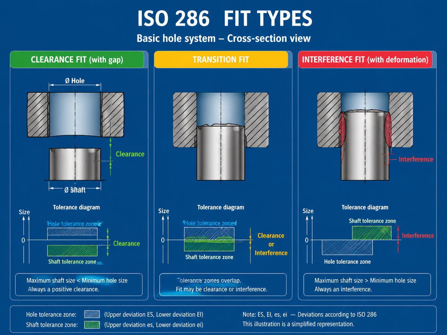
Thiết kế để đảm bảo độ vừa vặn: Khoảng hở, vùng chuyển tiếp và sự cản trở
Dáng ôm vừa vặn
Trục có đường kính nhỏ hơn lỗ — các bộ phận di chuyển tự do. Đối với công nghệ FDM, hãy thêm khe hở 0,3 – 0,5 mm mỗi bên cho máy in cấp cơ bản và 0,15 – 0,25 mm cho máy in tầm trung. Điều này đảm bảo quá trình trượt diễn ra trơn tru ngay cả khi bề mặt có độ nhám do các đường lớp gây ra.
Phù hợp với giai đoạn chuyển tiếp
Trục và lỗ có kích thước gần như bằng nhau — các bộ phận có thể lỏng hoặc chặt tùy thuộc vào kích thước thực tế. Đây là trường hợp lắp ghép khó nhất đối với công nghệ FDM vì dải dung sai (±0,25 mm) thường trùng lặp với khả năng của máy in. Hãy lên kế hoạch cho quá trình xử lý sau in nếu độ khít này là yếu tố quan trọng.
Lắp ghép có ma sát (lắp ghép ép)
Trục có đường kính lớn hơn lỗ — các bộ phận phải được ép khít vào nhau. Đối với công nghệ FDM, độ can thiệp từ 0,1 – 0,2 mm mỗi bên là phù hợp cho các máy in tầm trung sử dụng vật liệu PLA, PETG hoặc Nylon. Nếu độ can thiệp vượt quá 0,3 mm mỗi bên, có nguy cơ làm nứt thành lỗ. Nên tạo góc vát cho cả hai bộ phận để hỗ trợ quá trình lắp ráp.
Các mức dung sai lắp ráp được khuyến nghị cho công nghệ FDM
| Loại vừa vặn | Mức độ mới bắt đầu | Phân khúc tầm trung | Công nghiệp | Ví dụ |
|---|---|---|---|---|
| Trượt / lỏng lẻo | +0,5 mm | +0,3 mm | +0,15 mm | Ray trượt ngăn kéo, chốt bản lề |
| Bấm / nhấn | +0,2 mm | +0,1 mm | +0,05 mm | Nắp đậy nắp chai, nắp đậy pin |
| Lắp ép | −0,15 mm | −0,1 mm | −0,05 mm | Miếng lót ổ trục |
Quy trình hiệu chuẩn để đạt được dung sai tối ưu
Bước 1: Các bước E của bộ đùn — Đánh dấu 120 mm sợi trên đầu đùn, đùn 100 mm, đo chênh lệch. Điều chỉnh rotation_distance = current × (100 / actual extruded).
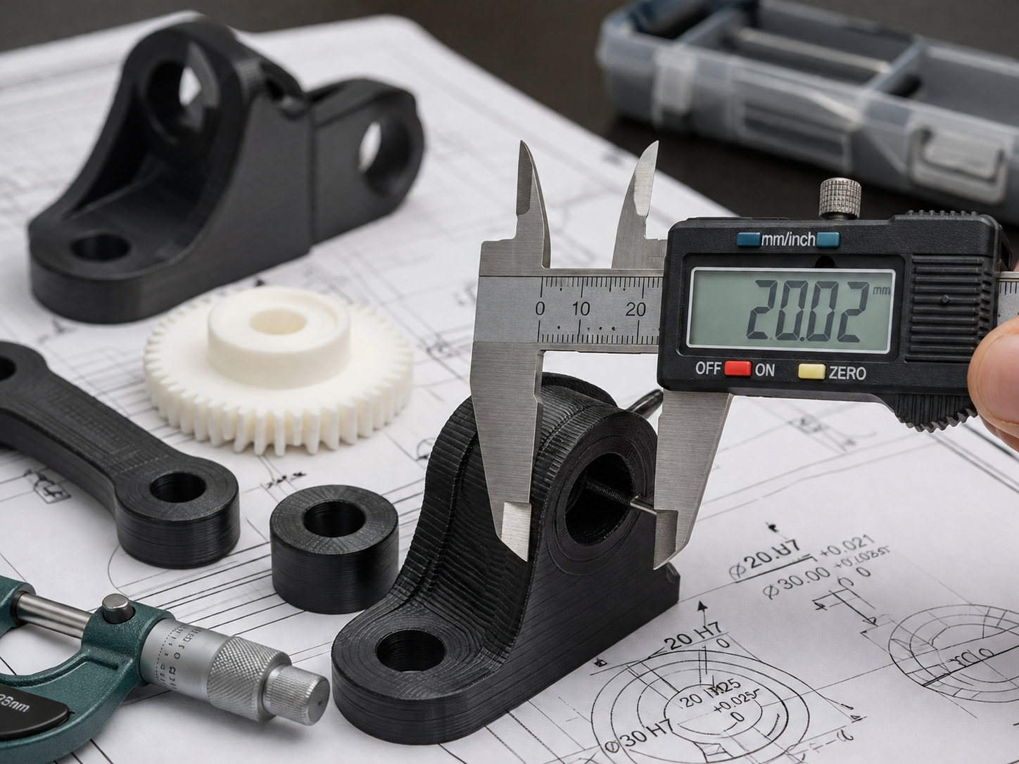
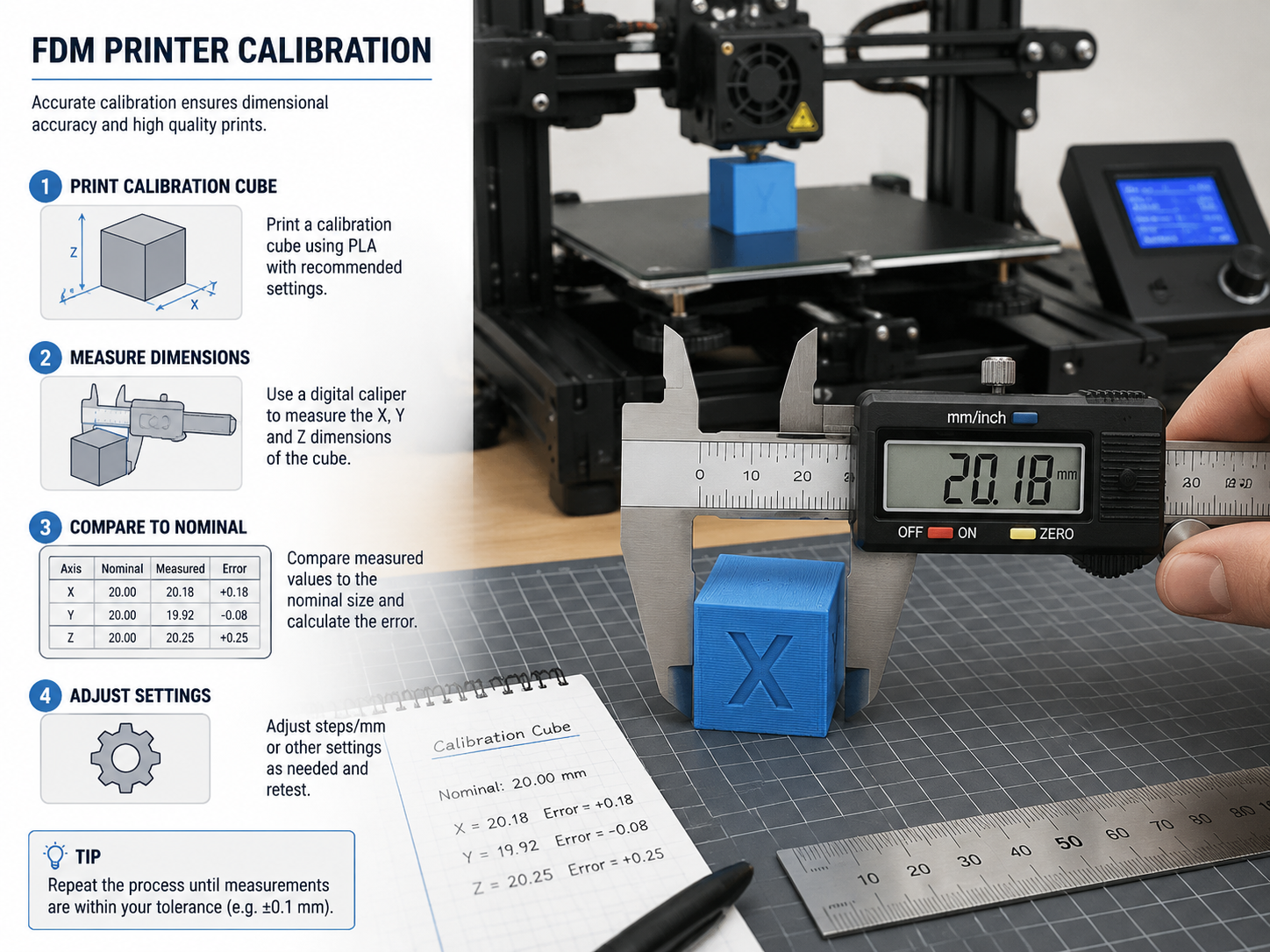
Bước 2: Hiệu chuẩn trục X và trục Y — In khối hiệu chuẩn 20 mm. Đo các trục X, Y, Z bằng thước kẹp điện tử. Điều chỉnh các bước một cách tương ứng cho đến khi tất cả các trục đều nằm trong phạm vi 0,1 mm so với giá trị danh định.
Bước 3: Hệ số nhân độ phồng — In mô hình hình lập phương một lớp thành (1 lớp viền, độ đặc 0%, không có mặt trên/dưới). Đo độ dày thành bằng micromet. Điều chỉnh hệ số đùn = giá trị hiện tại × (độ dày danh định / độ dày đo được). Mục tiêu: trong phạm vi ±0,05 mm.
Bước 4: Tiến tuyến tính / Tiến theo áp suất — In mẫu hiệu chuẩn giá trị K. Chọn giá trị sao cho các góc sắc nét và không bị phồng. Lỗi PA gây ra sai số kích thước từ 0,1–0,3 mm tại các góc.
Bước 5: Tháp đo nhiệt độ — In thử với mỗi cuộn sợi mới. Tìm điểm cân bằng tối ưu giữa độ bám dính giữa các lớp và độ ổn định kích thước. Các cuộn sợi cùng thương hiệu nhưng thuộc các lô sản xuất khác nhau có thể cần điều chỉnh nhiệt độ trong khoảng ±10 °C.
Các chiến lược thiết kế nhằm cải thiện độ chính xác của công nghệ FDM
Bù lỗ
Các lỗ in bằng công nghệ FDM thường có kích thước nhỏ hơn 0,2 – 0,4 mm so với thiết kế do hình dạng vòi phun và hiện tượng co ngót của vật liệu. Áp dụng độ giãn ngang cho thành lỗ: +0,15 mm mỗi bên đối với vòi phun 0,4 mm, +0,25 mm đối với vòi phun 0,6 mm. Hoặc thiết kế các lỗ lớn hơn 0,3 mm và thử lắp trước khi sản xuất.
Bồi thường theo phương pháp “Chân voi”
Vài lớp đầu tiên bị phình ra ngoài từ 0,1 đến 0,3 mm. Hãy sử dụng tính năng bù trừ trong phần mềm cắt lát (−0,15 mm cho 3–5 lớp đầu tiên). Thiết kế một góc vát 0,3 mm ở các cạnh dưới của các chi tiết ghép nối để đảm bảo độ chính xác khi lắp ráp.
Các tính năng có ren
Thiết kế các lỗ lớn hơn kích thước danh định 0,3 mm để tạo ren và lớn hơn 0,5 mm để đảm bảo khe hở. Sử dụng các miếng chèn ren cố định bằng nhiệt cho các lần lắp ráp lặp lại — chúng đáng tin cậy hơn nhiều so với các ren in bằng công nghệ FDM.
Xử lý hậu kỳ để đảm bảo độ chính xác
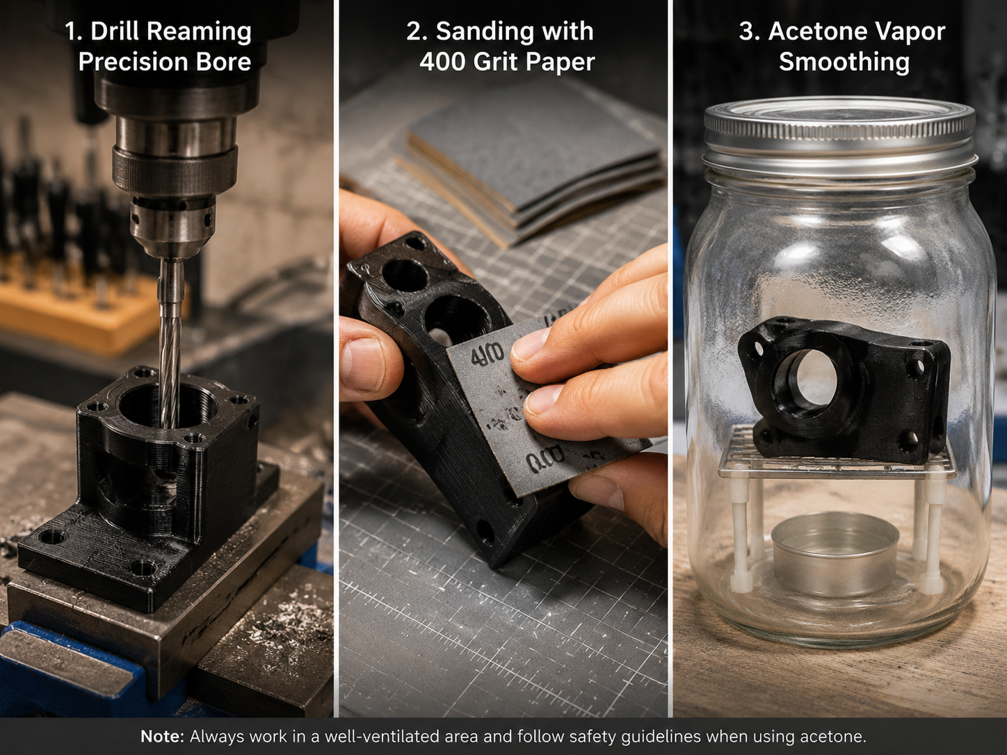
- Khoan và nong lỗ — Sử dụng dụng cụ nong lỗ hoặc mũi khoan chính xác có đường kính nhỏ hơn 0,1 mm so với kích thước mục tiêu, sau đó hoàn thiện với kích thước chính xác. Phương pháp này tạo ra các lỗ chính xác bất kể sai số trục XY của máy in.
- Trục chà nhám — Quấn giấy nhám cỡ 220 → 400 → 600 quanh khối phẳng. Mài bớt 0,05 – 0,1 mm mỗi lần mài, đồng thời kiểm tra độ khít bằng thước đo go/no-go.
- Làm mịn bằng hơi axeton — Chỉ dùng ABS. Đậy kín phần chi tiết phía trên lớp acetone trong bình thủy tinh trong vòng 3–10 phút. Lớp ngoài sẽ được nung chảy lại để tạo bề mặt mịn. Các chi tiết co lại khoảng 0,1 mm mỗi cạnh — cần tính đến điều này trong thiết kế.
- Gia công CNC — In với kích thước lớn hơn kích thước thiết kế và gia công với độ chính xác ±0,025 mm. Kết hợp sự linh hoạt về hình học của công nghệ FDM với độ chính xác của CNC để phục vụ các ứng dụng công nghiệp.
Kết luận
- Hãy nắm rõ độ dung sai thực tế của máy in — hãy đo đạc, đừng phỏng đoán
- Áp dụng dung sai lắp ghép: +0,3 đến +0,5 mm (lắp trượt), −0,1 đến −0,15 mm (lắp ép)
- Hiệu chuẩn một cách có hệ thống: e-steps → XY → hệ số đùn → độ trễ áp suất
- Khắc phục các lỗ hổng, các phần “chân voi” và các đường chỉ trong thiết kế của bạn
- Lập kế hoạch xử lý sau khi gia công khi yêu cầu độ chính xác dưới 0,1 mm
Các vấn đề của người mua là nguyên nhân dẫn đến tranh chấp về dung sai
- Một bản vẽ áp dụng một dung sai chặt chẽ cho mọi chi tiết mà không xác định chức năng lắp ráp.
- Trích dẫn này không đề cập đến các công nghệ FDM, SLS, MJF, SLA, hướng đặt mô hình, việc loại bỏ khung đỡ hay quá trình xử lý sau in.
- Các lỗ, chốt, nút bấm, ren và khớp trượt được chấp thuận mà không cần mẫu thử đại diện hoặc các bộ phận ghép nối.
- Phương pháp kiểm tra, hệ quy chiếu, điều kiện chuẩn bị và nhiệt độ đo lường chưa được xác định.
Nhựa nylon hỗ trợ dự án như thế nào
Từ năm 2005, Nylon Plastic đã hỗ trợ việc lựa chọn vật liệu và sản xuất các chi tiết nhựa hoàn thiện. Quá trình rà soát dự án này có thể kết nối các khía cạnh như lựa chọn quy trình, dung sai lắp ghép, chi tiết hiệu chuẩn, gia công thứ cấp và xác nhận lắp ráp, nhờ đó người mua không cần phải đánh giá từng quyết định sản xuất một cách riêng lẻ.
- Trước khi báo giá, hãy xem xét bản vẽ, vật liệu, số lượng, các đặc điểm quan trọng và môi trường sử dụng.
- So sánh các phương pháp in 3D, gia công CNC, chế tạo khuôn nhanh và đúc sản xuất khi có nhiều phương án khả thi.
- Xác định các mẫu thử, báo cáo theo chiều, tài liệu vật liệu, khả năng truy xuất nguồn gốc và các tiêu chí chấp nhận trước khi đưa sản phẩm ra thị trường.
Bài đọc liên quan
Dung sai trong in 3D phụ thuộc vào quy trình và độ khít
Không có tiêu chuẩn dung sai in 3D chung nào áp dụng cho các công nghệ FDM, SLA, SLS, MJF và DLS. Việc hiệu chuẩn máy, độ co ngót của vật liệu, hướng đặt mô hình, kích thước chi tiết, hành vi của lớp hoặc voxel, việc loại bỏ khung đỡ và quá trình xử lý sau in đều ảnh hưởng đến độ khít của sản phẩm hoàn thiện. Một khuyến nghị hữu ích về dung sai nên bắt đầu từ các chi tiết ghép nối và chuyển động lắp ráp, sau đó sử dụng một mẫu thử nhỏ để xác nhận sự kết hợp thực tế giữa máy in và vật liệu.
Xác định xem chi tiết đó là lỗ hở, lắp ép, lắp trượt, lắp bấm, ren, chốt, rãnh hay bề mặt thẩm mỹ. Nêu rõ kích thước danh nghĩa, tải trọng, lực lắp, chuyển động, nhiệt độ, điều kiện xử lý và phương pháp kiểm tra. Khoảng hở danh nghĩa trong bản vẽ CAD không giống với khoảng hở được đo sau khi in, loại bỏ bột, đóng rắn, gia công hoặc phủ lớp.
| Quy trình | Rủi ro về kích cỡ thông thường | Cần xác thực những gì |
|---|---|---|
| FDM | Hướng lớp, độ lan rộng của lớp đầu tiên, hình dạng góc và độ co ngót dị hướng | Định hướng, vòi phun, chiều cao lớp, số lớp thành và mẫu thử lỗ |
| SLA | Sự phát triển của sản phẩm sau khi đóng rắn, hiện tượng phồng nhựa, vết hằn của khung đỡ và sự thay đổi sau khi đóng rắn | Rửa, chu trình xử lý, vị trí cố định và kích thước đặc tính được đo |
| SLS | Loại bỏ bột, co ngót nhiệt, bịt kín lỗ nhỏ và tạo kết cấu bề mặt | Hướng lắp ráp, tình trạng bột, lỗ/chốt và mẫu thử khe hở |
| MJF | Biến dạng nhiệt, tỷ lệ chi tiết, loại bỏ bột và co ngót cục bộ | Máy móc, vật liệu, hướng đặt, độ dày thành và điều kiện mẻ sản xuất |
| DLS | Hành vi tạo lớp và đóng rắn, quá trình tháo khung đỡ và sự thay đổi kích thước | Vật liệu, quá trình đóng rắn, chiến lược hỗ trợ và kiểm tra sau gia công |
Lỗ, chốt, rãnh, ren và thành
Các lỗ nhỏ thường được in với kích thước nhỏ hơn so với thiết kế do kích thước voxel, hình dạng hạt, cách nén bột, quá trình đóng rắn nhựa hoặc các bước xử lý sau in. Một lỗ ngang dài cũng có thể thay đổi hình dạng khi thay đổi hướng in. Các chốt có thể bị in quá khổ do vật liệu tích tụ ở các góc hoặc do cơ chế bù trừ của máy in không đồng đều. Các khe và thành mỏng cần có mẫu thử riêng vì kích thước in thành công ở một hướng có thể bị đóng lại hoặc biến dạng ở hướng khác.
Nên lựa chọn ren dựa trên quy trình và số chu kỳ lắp ráp. Các ren in có thể cần khoảng hở lớn hơn, cấu trúc ren thô, quy trình gia công ren sau hoặc miếng chèn kim loại. Đối với khớp lắp nhanh, cần xác định độ biến dạng, bán kính, hướng và số chu kỳ lặp lại thay vì chỉ dựa vào sự khớp mắt thường. Dung sai cuối cùng phải được ghi rõ trong bản vẽ và liên kết với máy móc, vật liệu và hướng đã được kiểm chứng.
| Tính năng | Câu hỏi mở đầu | Bằng chứng được khuyến nghị |
|---|---|---|
| Lỗ thông và chốt | Nó phải trượt, định vị hay xoay? | Phiếu mẫu lỗ kim ở kích thước danh nghĩa thực tế |
| Lắp ép | Lực lắp ghép và ứng suất vật liệu ở mức nào là chấp nhận được? | Đo lực, kiểm tra tiết diện và thử nghiệm chu kỳ |
| Khe cắm hay chốt | Tính năng này có cần độ linh hoạt, khoảng hở hay điểm dừng cứng không? | Thử nghiệm lắp ráp phiếu giảm giá và thử nghiệm sử dụng nhiều lần |
| Chỉ in | Cần bao nhiêu chu kỳ và mô-men xoắn là bao nhiêu? | Thước đo ren, kiểm tra mô-men xoắn và hồ sơ sau gia công |
| Thành mỏng | Liệu nó có chịu được quá trình in ấn, làm sạch và xử lý không? | Mẫu thử độ dày thành ống và kiểm tra kích thước |
Định hướng, co ngót và xử lý sau gia công
Hướng in ảnh hưởng đến độ bền lớp, độ bám dính của khung đỡ, độ nhẵn bề mặt, dòng nhiệt và sai số kích thước. Nên chọn hướng in dựa trên tải trọng chức năng và các đặc điểm quan trọng, chứ không chỉ dựa vào thời gian in ngắn nhất. Đối với quy trình in bằng bột, hãy xem xét mật độ đóng gói và độ dốc nhiệt. Đối với quy trình in bằng nhựa lỏng, hãy tính đến quá trình rửa và đóng rắn. Đối với công nghệ FDM, hãy tính đến hành vi của lớp đầu tiên, quá trình làm mát và hướng của đường in so với tải trọng.
Hãy đo kích thước chi tiết đã in sau khi hoàn tất các công đoạn xử lý sau in, vốn sẽ được sử dụng cho quá trình lắp ráp. Nếu chi tiết sẽ được ủ, đánh bóng, phủ lớp, gia công cơ khí hoặc xử lý điều kiện, hãy tính đến các công đoạn đó trước khi xác định dung sai cuối cùng. Nhà cung cấp nên báo cáo thông tin về máy móc, vật liệu, hướng đặt, điều kiện in, quy trình xử lý sau in, số lượng mẫu, điểm tham chiếu và phương pháp kiểm tra thay vì đưa ra một cam kết chung chung.
Phiếu giảm giá và bằng chứng kiểm tra
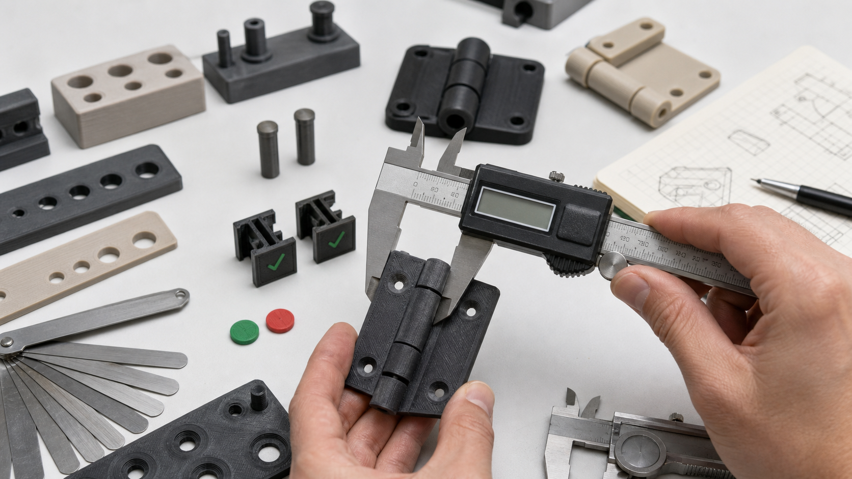
Một mẫu thử thực tế có thể bao gồm một loạt các chốt và lỗ, rãnh, ren ngoài và ren trong, thành mỏng, các chi tiết ghép khớp và các bậc bề mặt. In mẫu thử này với cùng hướng, vật liệu, điều kiện lớp hoặc bột và quy trình xử lý sau in như chi tiết sản xuất. Đo các đặc điểm bằng thiết bị đo lường dự định và ghi lại kết quả theo từng vị trí. Mẫu thử sẽ hữu ích nhất khi được liên kết với một quyết định chấp nhận rõ ràng: khả năng di chuyển tự do, lực lắp ghép, rò rỉ, mô-men xoắn hoặc giới hạn kích thước.
Danh sách kiểm tra yêu cầu báo giá (RFQ) về dung sai in 3D
- Quy trình, máy móc, vật liệu, lô sản phẩm và hướng định vị dự kiến.
- CAD, hệ tọa độ tham chiếu, kích thước chi tiết, loại ghép, tải trọng và chu kỳ lắp ráp.
- Các yêu cầu về lỗ, chốt, khe, ren, thành lỗ và khe hở.
- Giai đoạn xử lý sau, điều chỉnh, phủ lớp và đo lường.
- Thiết kế phiếu giảm giá, số lượng mẫu, phương pháp thử và giới hạn chấp nhận.
- Số lượng mẫu thử, bao bì, báo cáo kiểm tra và quá trình chuyển giao sản xuất.
Vui lòng cung cấp thông tin về quy trình sản xuất, vật liệu, bản vẽ CAD, loại độ khít, kích thước chi tiết, số lượng và yêu cầu kiểm tra. Chúng tôi có thể đề xuất mức dư ban đầu, mẫu thử độ khít và kế hoạch xác minh phù hợp với máy gia công cụ thể, thay vì chỉ dựa vào dung sai chung của chi tiết đúc sẵn.
Câu hỏi thường gặp
Nên sử dụng dung sai nào cho một cụm chi tiết in 3D?
Không có giá trị chung nào cả. Dung sai được xác định bởi quy trình, máy móc, vật liệu, hướng, kích thước chi tiết, bề mặt hoàn thiện và loại lắp ghép. Cần kiểm tra các mẫu thử đại diện và cụm lắp ráp thực tế.
Tại sao các lỗ được in ra thường có kích thước nhỏ hơn so với thiết kế?
Việc xấp xỉ độ dày lớp, chiều rộng đùn, độ co ngót, tính chất của bột hoặc nhựa, ảnh hưởng của khung đỡ và quá trình hiệu chuẩn đều có thể làm giảm số lượng lỗ. Các lỗ có kích thước quan trọng có thể cần phải điều chỉnh thiết kế hoặc thực hiện các công đoạn khoan và nong lỗ bổ sung.
Có thể in trực tiếp lên sợi chỉ không?
Các ren lớn và thô có thể được sử dụng khi quy trình gia công và tải trọng cho phép. Đối với các ren nhỏ, lặp lại nhiều lần hoặc yêu cầu mô-men xoắn cao, việc sử dụng miếng chèn, khoan ren hoặc gia công thường mang lại hiệu quả tốt hơn.
Cần kiểm tra các kích thước in quan trọng như thế nào?
Trước khi sản xuất, cần xác định các mốc tham chiếu, hướng, điều kiện, trạng thái xử lý sau, thiết bị đo lường, kích thước mẫu và các kiểm tra đối với các chi tiết ghép nối.
Yêu cầu đánh giá dung sai in 3D
Vui lòng gửi bản vẽ CAD, bản vẽ kỹ thuật, yêu cầu về quy trình, vật liệu, số lượng, các chi tiết ghép nối và các kích thước quan trọng để tiến hành đánh giá độ khớp và kiểm tra.