Why Manufacturers Are Switching from Metal to Plastic
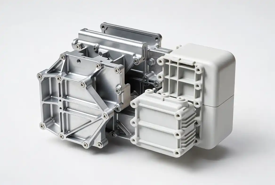
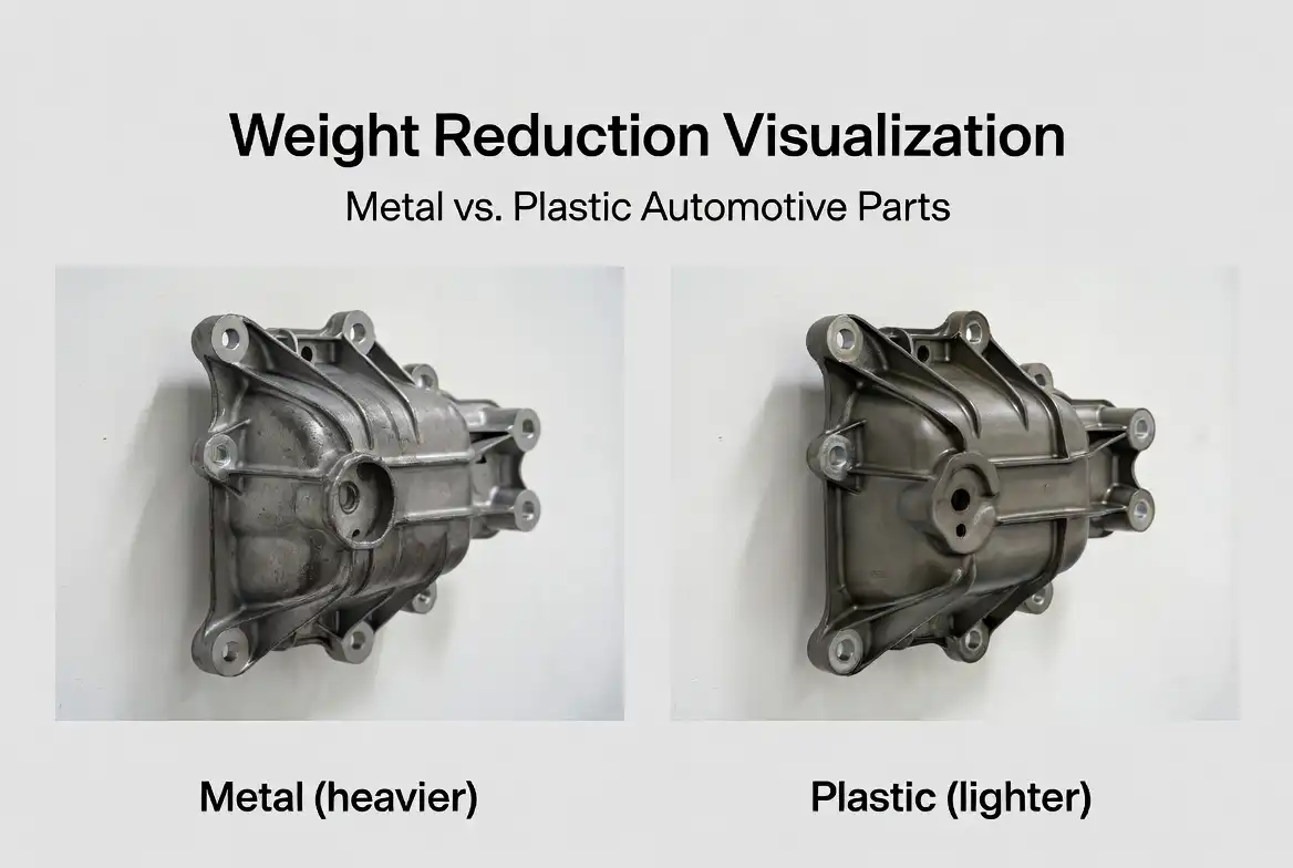
Metal-to-plastic conversion is one of the most impactful cost-reduction strategies available to product designers and procurement engineers today. Across automotive, industrial equipment, medical devices, and consumer electronics, engineering teams are replacing machined metal components with injection-molded or CNC-machined engineering plastics. The drivers are compelling: 30% to 60% lower part cost, 50% to 80% weight reduction, elimination of corrosion treatments, and dramatic part consolidation opportunities that simplify assembly and reduce SKU counts.
The decision to convert is not simply about swapping materials on a drawing. Successful metal-to-plastic conversion requires a systematic approach that accounts for structural requirements, thermal conditions, chemical exposure, manufacturing process selection, and mold design. This guide provides a complete framework for evaluating and executing metal replacement projects using nylon, POM, PEEK, PPS, and related engineering thermoplastics.
When Metal-to-Plastic Conversion Makes Sense
Not every metal part should become plastic. The strongest candidates share several characteristics. Parts with complex geometry that require multiple machining operations are prime targets because injection molding consolidates those steps into a single cycle. Assemblies with multiple metal components joined by fasteners or welding are ideal because plastic allows designers to combine several pieces into one molded part. Components operating in corrosive environments or requiring chemical resistance often perform better in engineering plastics than in coated or plated metals. Parts where weight matters, such as automotive under-hood brackets, aerospace interior components, and handheld devices, see immediate performance benefits from plastic conversion.
| Tiêu chí | Strong Candidate for Plastic | Better Left in Metal |
|---|---|---|
| Operating Temperature | Below 150°C continuous (PEEK to 260°C) | Sustained above 260°C |
| Mechanical Load | Moderate structural, static loads | Extreme tensile stress near material yield |
| Geometry Complexity | Multi-step machined, multi-piece assembly | Simple turned or stamped single-piece |
| Khối lượng sản xuất | Medium to high (5,000+ units/year) | Very low (under 500 units/year) |
| Chemical Environment | Acids, salt spray, fuels, solvents | No restrictions; metal acceptable |
| Dimensional Tolerance | ±0.05 mm achievable with engineering plastics | ±0.005 mm or tighter required |
| Tính chất điện | Insulation needed, EMI not critical | Conductivity or EMI shielding required |
Material Selection for Metal Replacement
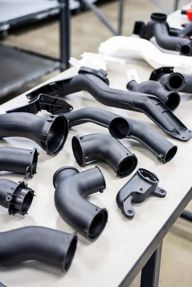
Selecting the right engineering plastic is the single most critical decision in any metal-to-plastic conversion project. The material must satisfy structural, thermal, and chemical requirements simultaneously while remaining processable at the target production volume. The following comparison covers the most commonly specified replacement grades.
| Metal Being Replaced | Recommended Plastic | Lợi thế chính | Limitation to Watch |
|---|---|---|---|
| Aluminum (6061, die-cast) | PA66 chứa 30% sợi thủy tinh | Comparable stiffness, 40% lighter | Moisture absorption; dimensional change |
| Steel (low carbon, stamped) | POM (acetal) | Excellent fatigue resistance, self-lubricating | Notch sensitivity; avoid strong acids |
| Stainless Steel (304, 316) | PPS GF40 | Broad chemical resistance, 260°C HDT | Higher material cost; brittle in thin sections |
| Aluminum (structural, aerospace) | PEEK CF30 | Continuous use at 260°C, chemical inertness | Premium cost; requires high-temp tooling |
| Brass/Bronze (bearings, bushings) | PA6 MoS2, POM | Self-lubricating, no grease needed | Higher thermal expansion than metal |
| Zinc Die-Cast | PA6 GF30, PBT GF30 | Complex thin-wall geometry achievable | Lower stiffness than zinc in some designs |
| Cast Iron (housings, covers) | PPA GF40, PPS GF40 | Dramatic weight reduction, corrosion-proof | CTE mismatch with mating metal parts |
Case Study: Automotive Engine Bracket
A Tier-1 automotive supplier converted an aluminum engine mounting bracket to PA66 GF35. The original part required casting, three machining operations, and a corrosion-protection coating. The plastic version consolidated what had been a two-piece bolted assembly into a single injection-molded component. Results included a 47% reduction in part cost, 62% weight reduction from 840 g to 320 g, elimination of all secondary operations, and a 12-second cycle time producing two parts per shot. The bracket passed all thermal cycling and vibration durability tests required by the OEM.
Case Study: Industrial Pump Housing
A manufacturer of chemical transfer pumps replaced a 316 stainless steel pump housing with PPS GF40 for a corrosive fluid handling application. The stainless steel housing required investment casting followed by CNC machining of sealing surfaces, resulting in a 14-week lead time. The PPS housing, produced by injection molding with insert-molded threaded bushings, reduced lead time to 4 weeks, cut part cost by 55%, and delivered superior chemical resistance to the specific process fluid, which had caused pitting corrosion on the original stainless steel. Annual production of 25,000 units made the mold investment pay back in under 8 months.
Design for Manufacturing in Plastic Conversion
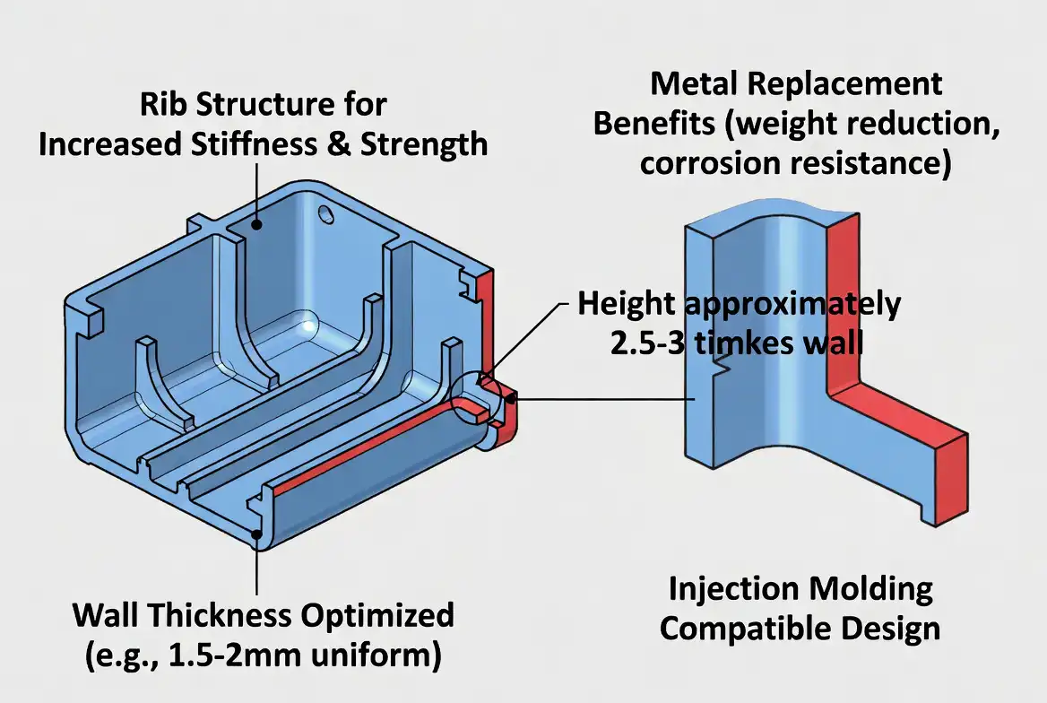
Simply replicating a metal part’s geometry in plastic almost always fails. Plastic requires fundamentally different design rules. Nominal wall thickness should be maintained between 1.5 mm and 4.0 mm, with uniformity being far more important than in metal design. Sharp internal corners that metal forgives become stress concentrators in plastic; generous radii of at least 0.5 times wall thickness are mandatory. Ribs should be 50% to 70% of the adjoining wall thickness to avoid sink marks while providing the stiffness metal parts achieve through section thickness alone. Draft angles of 0.5 to 3.0 degrees must be incorporated on all surfaces parallel to the mold opening direction, a constraint that does not exist in machining or casting. The gate location must be placed to avoid weld lines at high-stress regions, and the parting line must be planned early in the design phase, not as an afterthought.
The Mold Design Difference
Metal-to-plastic conversion introduces tooling considerations that do not exist in metal part procurement. For glass-fiber-reinforced grades, which represent the majority of structural metal replacements, mold steel selection changes significantly. Hardened tool steels such as H13 or Stavax are required to resist abrasive wear from glass fibers. Runner systems must be designed for balanced filling when using filled materials. Shrinkage compensation factors vary substantially between unfilled and filled grades, typically ranging from 0.3% for highly filled PPS to 2.0% for unfilled PA66. Hot runner systems, while adding initial tool cost, often pay back quickly on medium-to-high-volume metal replacement projects by eliminating cold runner waste from expensive engineering resins. Cooling channel design requires mold flow analysis for all but the simplest geometries because differential shrinkage in thick-to-thin transitions causes warpage that metal parts do not experience.
Testing and Validation Protocol
Metal replacement parts must undergo a structured validation program before production approval. The testing sequence should include material characterization using tensile, flexural, and impact testing per ISO or ASTM standards at both ambient and elevated temperatures matching the application’s maximum service temperature. Dimensional verification should compare first-article plastic parts against the original metal part GD&T requirements, accounting for the higher coefficient of thermal expansion of plastics. Functional testing must replicate the actual assembly and operating conditions, including any chemical exposure, UV exposure for external components, and thermal cycling through the full operating range. For structural applications, fatigue testing to the design life requirement is non-negotiable. Accelerated aging according to the relevant industry standard provides confidence in long-term performance. A gate-seal study and process window DOE on the molding process ensure robustness before production ramp-up.
Cost Analysis Framework
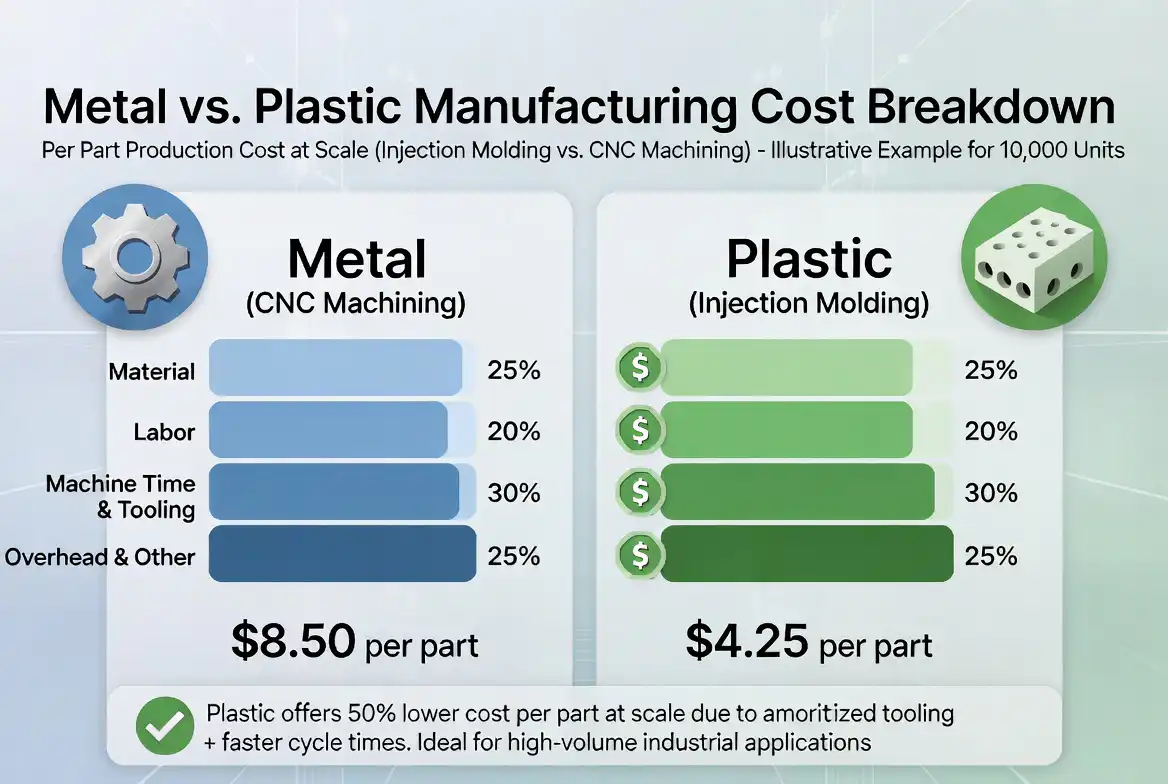
The total cost comparison between metal and plastic must go beyond piece price. A complete analysis includes raw material cost per part, mold or tooling amortization over the program life, cycle time and machine rate for the production process, all secondary operations such as deflashing, machining, or assembly, surface finishing costs including plating or painting that plastic may eliminate, scrap rate differences typically lower for injection molding than multi-step metal processing, freight cost savings from lighter parts, and warranty and field failure cost estimates based on prototype testing data. When all factors are included, metal-to-plastic conversion typically delivers payback within 3 to 18 months for production volumes above 10,000 units per year.
Advanced Material Selection Strategies
Beyond the basic material selection chart, specialists consider several advanced factors. Fiber reinforcement type and loading directly affect stiffness, dimensional stability, and isotropy of properties. Short glass fibers at 30% to 50% loading provide the best balance of stiffness and processability for most structural metal replacements. Long glass fiber compounds, typically at 30% to 50% loading, offer 20% to 40% higher impact strength and better fatigue resistance than short fiber compounds at the same loading, making them the material of choice for components subjected to impact and vibration. Carbon fiber reinforcement at 20% to 40% loading provides the highest specific stiffness and strength of any reinforcement type, with the added benefit of lower thermal expansion coefficient that reduces the CTE mismatch with metal mating components. However, carbon fiber compounds are abrasive to tooling and more expensive than glass fiber grades.
Mineral fillers including talc, calcium carbonate, and wollastonite provide moderate stiffness improvement at lower cost than fiber reinforcement, and they reduce warpage by making shrinkage more isotropic. For metal replacement parts with flatness requirements, mineral-filled compounds often outperform fiber-reinforced grades. Impact modifiers added to glass-reinforced compounds improve ductility and crack resistance at the cost of some stiffness and strength. For applications requiring both stiffness and impact resistance, such as brackets subject to stone impact, impact-modified reinforced grades provide the necessary performance balance.
Thermal Management in Plastic Conversion
Plastics conduct heat 100 to 500 times less efficiently than metals. This has significant implications for metal replacement design in applications where the original metal part served as a heat sink or where the part is located near heat sources. For under-hood automotive brackets adjacent to exhaust components, the plastic part must withstand not just the ambient under-hood temperature but also radiative heating from nearby hot surfaces. Heat shields, reflective coatings, or air gap design may be required. For electronic enclosures, the reduced thermal conductivity of plastic compared to aluminum means that thermal management must be addressed through ventilation, heat sinks insert-molded into the plastic, or thermally conductive filled compounds that bridge the gap between insulating plastics and conductive metals.
Thermally conductive plastics filled with graphite, ceramic, or metal fibers can achieve thermal conductivity of 1 to 20 watts per meter-kelvin, compared to 0.2 to 0.3 for unfilled engineering plastics and 150 to 200 for aluminum. While these values still fall far short of metals, they are sufficient for many applications where the plastic part was previously excluded solely on thermal grounds. The cost premium for thermally conductive compounds, typically 2 to 5 times the base polymer cost, must be weighed against the system-level benefits of plastic conversion.
Câu hỏi thường gặp
Nhiệt độ tối đa mà một bộ phận thay thế bằng nhựa có thể chịu được là bao nhiêu?
PEEK có thể hoạt động liên tục ở 260°C và chịu được những đợt tăng nhiệt ngắn hạn lên đến 300°C. PPS chịu được nhiệt độ liên tục 220°C. PPA và PA46 được thiết kế để sử dụng liên tục trong khoảng nhiệt độ từ 150°C đến 180°C. Nếu ứng dụng của bạn yêu cầu nhiệt độ duy trì liên tục vượt quá 260°C, thông thường cần sử dụng vật liệu kim loại hoặc gốm. Loại vật liệu cụ thể, hàm lượng chất độn và môi trường hóa học đều ảnh hưởng đến khả năng chịu nhiệt thực tế, do đó hãy tham khảo bảng dữ liệu vật liệu và tiến hành thử nghiệm phù hợp với ứng dụng cụ thể.
Thực tế thì tôi có thể giảm được bao nhiêu trọng lượng khi chuyển từ kim loại sang nhựa?
Mức giảm trọng lượng điển hình dao động từ 50% đến 80%, tùy thuộc vào loại kim loại ban đầu. Việc chuyển đổi từ nhôm sang PA66 GF30 thường giúp tiết kiệm từ 40% đến 55%. Việc chuyển đổi từ thép sang PPS GF40 có thể tiết kiệm từ 65% đến 75%. Việc chuyển đổi từ kẽm đúc áp lực sang PBT GF30 giúp tiết kiệm khoảng từ 55% đến 65%. Mức giảm trọng lượng thực tế phụ thuộc vào việc thiết kế nhựa có duy trì độ dày thành như cũ hay được tối ưu hóa bằng các gân và đặc điểm cấu trúc mà hình dạng kim loại không cho phép.
Tôi có cần thiết kế lại hoàn toàn chi tiết đó không, hay chỉ cần thay đổi vật liệu trên bản vẽ là được?
Việc thay thế trực tiếp vật liệu hầu như không bao giờ hiệu quả đối với các chi tiết kết cấu. Nhựa đòi hỏi độ dày thành đồng nhất, bán kính bo tròn lớn, góc nghiêng và các thanh gia cố – những yêu cầu mà thiết kế kim loại không cần đến. Bạn phải thiết kế lại chi tiết theo các quy tắc DFM dành riêng cho nhựa. Tuy nhiên, việc thiết kế lại này thường cho phép hợp nhất các chi tiết, từ đó giảm tổng số lượng linh kiện trong cụm lắp ráp và hạ thấp chi phí tổng thể của hệ thống.
Làm thế nào để xử lý các miếng lót ren và các chi tiết buộc chặt trong các chi tiết nhựa?
Có một số phương pháp được coi là tiêu chuẩn. Các loại vít tạo ren được thiết kế dành riêng cho nhựa giúp loại bỏ nhu cầu sử dụng miếng chèn ren trong nhiều ứng dụng. Miếng chèn ren bằng đồng thau hoặc thép không gỉ được cố định bằng nhiệt hoặc bằng sóng siêu âm mang lại độ bền cho ren kim loại trong các trường hợp yêu cầu lắp ráp và tháo rời lặp đi lặp lại. Các miếng chèn được đúc sẵn được đặt vào khuôn trước khi ép phun cung cấp giải pháp chắc chắn nhất cho các ứng dụng yêu cầu mô-men xoắn cao. Quá trình đúc phủ có thể bao bọc các thành phần kim loại trong chu kỳ ép phun, tạo ra một chi tiết tích hợp duy nhất.
Khối lượng sản xuất tối thiểu nào là đủ để có thể chuyển đổi từ kim loại sang nhựa?
Đối với các chi tiết đơn giản, khoản đầu tư vào khuôn mẫu từ $5.000 đến $15.000 có thể thu hồi vốn với sản lượng từ 2.000 đến 5.000 đơn vị mỗi năm. Đối với các khuôn phức tạp nhiều khoang có hệ thống dẫn nóng bằng thép tôi cứng, chi phí khuôn mẫu từ $30.000 đến $80.000 thường yêu cầu sản lượng từ 10.000 đến 50.000 đơn vị mỗi năm để thu hồi vốn trong vòng 12 tháng. Gia công CNC từ vật liệu nhựa là một giải pháp thay thế cho các lô sản xuất dưới 2.000 đơn vị, giúp loại bỏ hoàn toàn chi phí khuôn mẫu đồng thời vẫn mang lại lợi thế về trọng lượng và khả năng chống ăn mòn so với kim loại.